[DIAGRAM] Single Phase Capacitor Motor Wiring Diagrams Transmission Lines

The wiring diagram for a single phase 2 speed motor will typically include the following components: a main winding, a start winding, a motor switch, and a capacitor. The main winding is responsible for the normal operation of the motor at its low speed, while the start winding is used to provide the initial torque required to start the motor.
[DIAGRAM] Subwoofer And Capacitor Wire Diagram
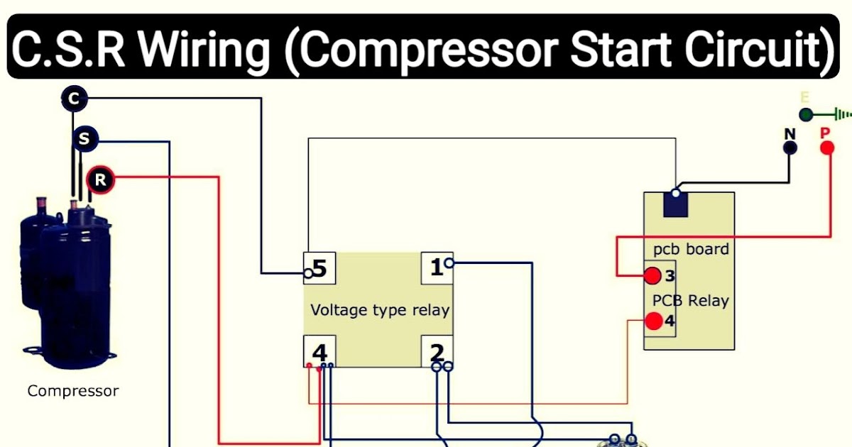
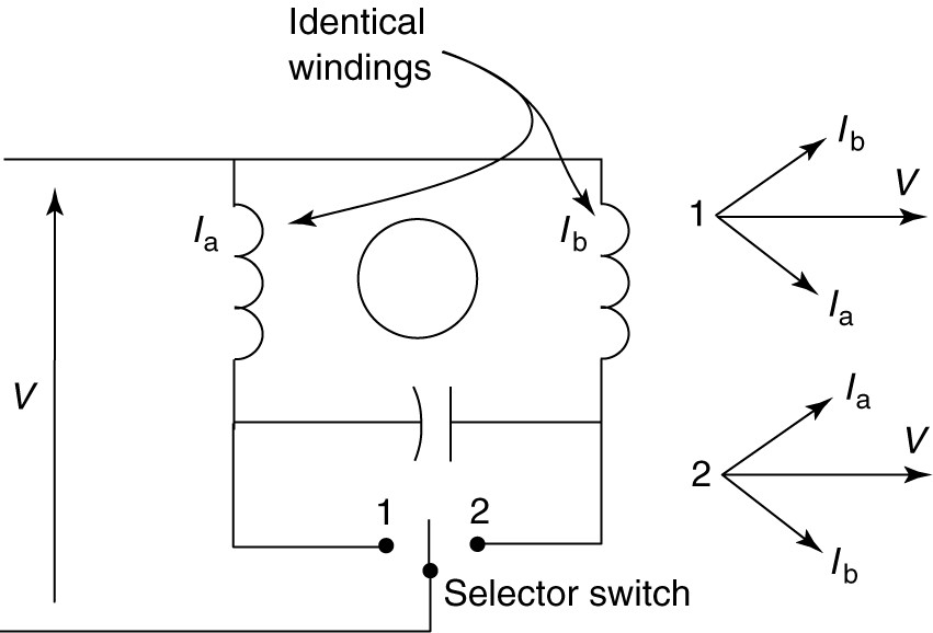
FIGURE 4: Reversing permanent split-capacitor motor circuit (wiring) diagram. Capacitor Start-Capacitor Run Motor. To provide both good starting torque and good running performance, two capacitors could be used, as shown in Figure 5. One capacitor provides high starting torque and is switched out when the motor reaches rated speed.
Single Phase Asynchronous Motor Transmisi Daya

In this post, I share a One-phase motor capacitor start and capacitor Run wiring connection diagram. In the above single-phase motor capacitor and capacitor run diagram, I have shown the motor auxiliary and main winding. I have shown the starting capacitor with the centrifugal switch and the Running capacitor direct to the motor auxiliary winding.
Yc Series 5HP 3.7kw Single Phase Capacitor Start and Run Induction Motor China AC Motor and

The wiring diagram for a Baldor single phase motor with a capacitor typically includes several key components, including the main power source, the capacitor, the start winding, and the run winding. The capacitor is connected to both the start and run windings and helps provide the necessary electrical energy to start the motor and keep it.
Weg Single Phase Motor Wiring Diagram With Capacitor Wiring Draw And Schematic

How to wire single phase motor with capacitor. You will find out how to identify to main and auxilliary winding and change motor rotation.Start capacitor, ru.
ac Correct Wiring of 1 phase 220v Electrical Motor Electrical Engineering Stack Exchange

A typical wiring diagram for a single phase motor includes various components such as the power supply, starting capacitor, run capacitor, start winding, run winding, and overload protection. These components are connected in a specific sequence to ensure proper motor operation.
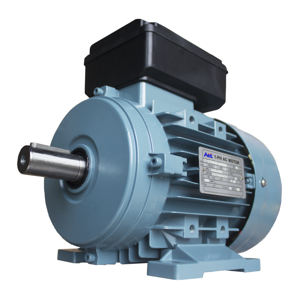
DY Series Single Phase (Capacitor Run) Aluminum Induction Motor ATT Electric Motor
Below is how to wire a split phase motor. Capacitor Start Capacitor Run Motor Wiring Diagram. Now we will learn about the single phase motor 2 capacitor wiring diagram or capacitor start capacitor run motor. A capacitor start capacitor run motor is also known as a two value capacitor motor. The "two value" comes from the installation of two.
Wiring Diagram For 220 Volt Single Phase Motor, http//bookingritzcarlton.info/wiringdiagram

The thousands of motors I've wired up over the years are mostly either your 9 lead 3 phase verity, or your straight forward single phase with a capacitor or 2. My buddy is really counting on me and I'm doing this for free, since he is disabled, and just a really good human being altogether.
3 Phase Electric Motor Wiring Diagram
single-phase motor from another is the method of starting. A single. Capacitor-start motor wiring diagram. speed, the starting capacitor is switched out but a running capacitor remains in the circuit and in series with the auxiliary winding. The wiring diagram is displayed in Fig. 6.4. Leaving the auxiliary winding
air compressor capacitor wiring diagram Wiring Diagram
The capacitor start motor has a cage rotor and has two windings on the stator. They are known as the main winding and the auxiliary or the starting winding. The two windings are placed 90 degrees apart. A capacitor C S is connected in series with the starting winding. A centrifugal switch S C is also connected to the circuit.
Diagram Of A Single Phase Motot Wiring Draw

The motor wiring diagram provides a visual representation of the electrical connections for a single-phase motor. It illustrates how the different components, such as the power supply, start capacitor, run capacitor, centrifugal switch, and winding connections, are connected to each other. Typically, single-phase motors have two types of.
Weg Single Phase Motor Wiring Diagram With Capacitor Diagram Techno

Single-phase induction motors are not self-starting without an auxiliary stator winding driven by an out of phase current of near 90 °. Once started the auxiliary winding is optional. The auxiliary winding of a permanent split capacitor motor has a capacitor in series with it during starting and running. A capacitor-start induction motor only.
Single Phase Motor Wiring Diagram with Capacitor Start Wiring Diagram Image
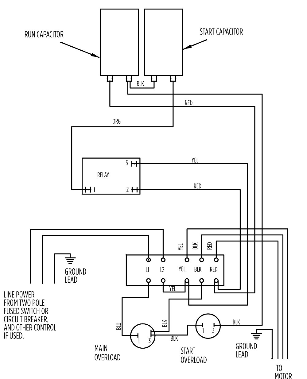
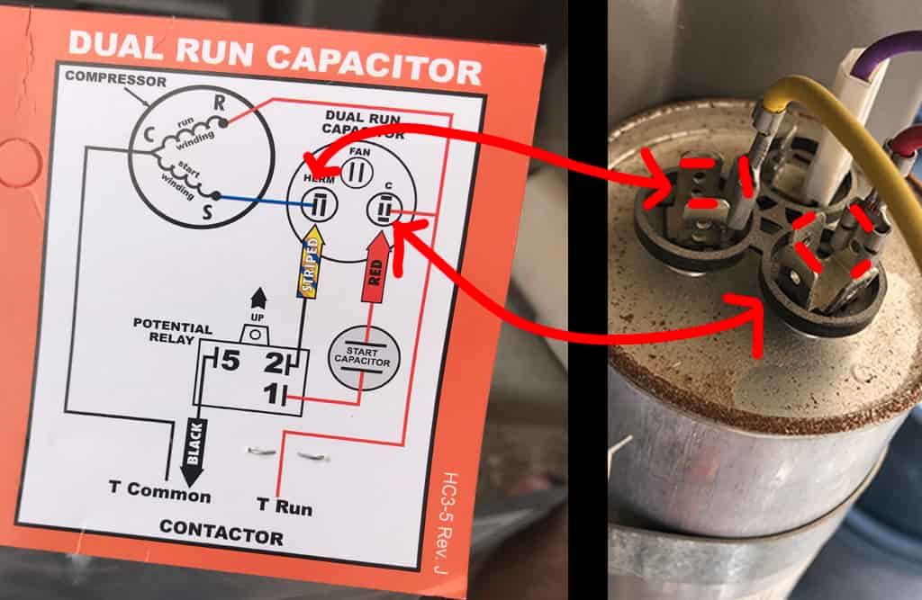
Example Source: DAYTON ELECTRIC MOTOR WIRING DIAGRAM [PDF], Dayton Electric Mfg. Co., 5959 W. Howard St., Niles IL 60714 USA, retrieved 2017/07/09, original source: Grainger.com. Start & Run & Dual Capacitor Specification References. At left is a simple two-terminal run capacitor.
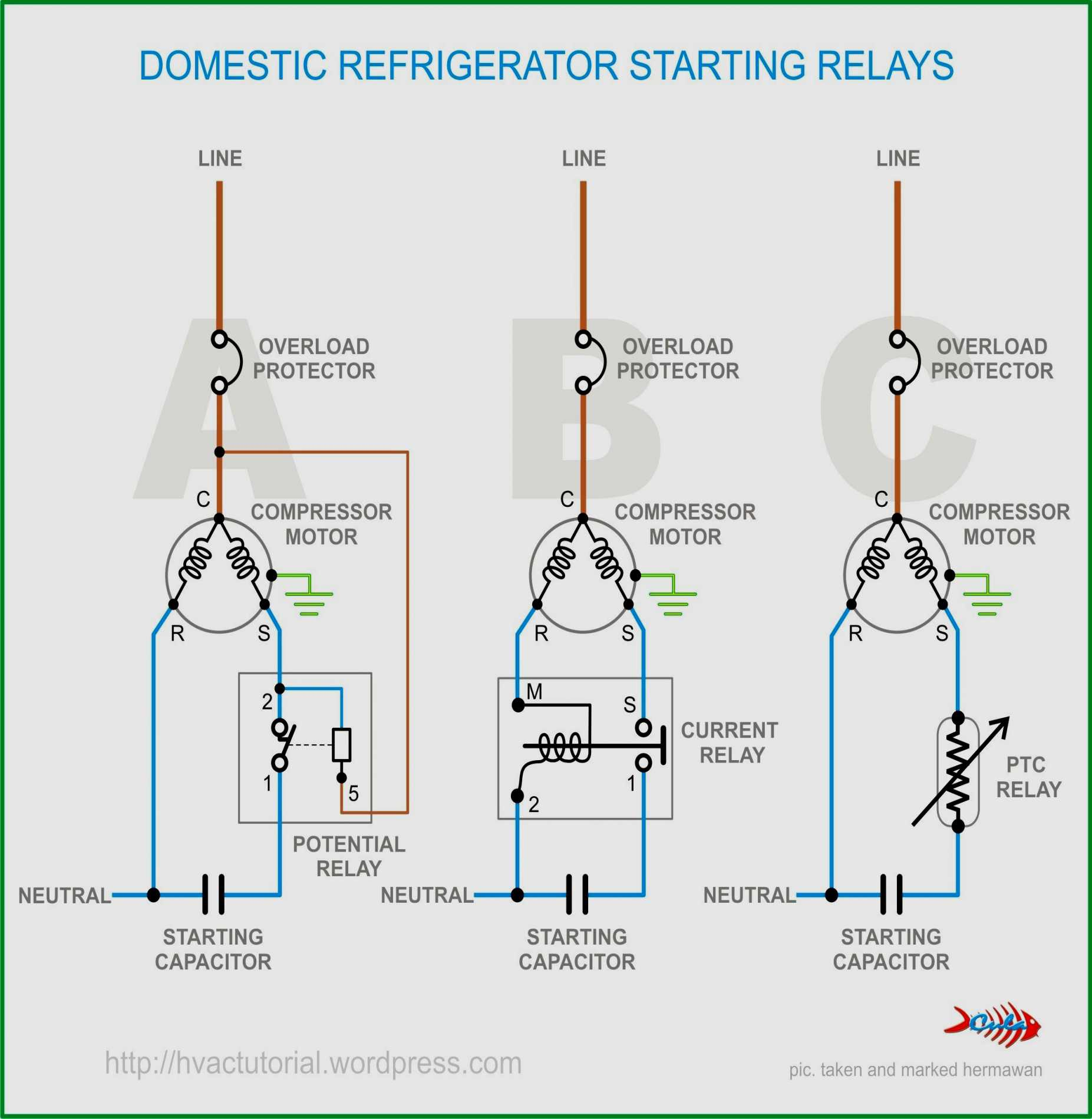
Types of Single Phase Induction Motors Single Phase Induction Motor Wiring Diagram
Wiring motor phase capacitor single diagram switch start winding run reverse red direction l1 l2 two please help neutral pdfCapacitor motor start phase diagram single wiring induction run circuitglobe circuit collection source phasor contents Phase capacitor capacitors winding uloženéAc motor run capacitor wiring diagram : diagram ac motor.
How To Wire A Single Phase Motor Seed Wiring

A capacitor-start capacitor-run (CSCR) motor is a type of single-phase induction motor that uses two capacitors - a starting capacitor and a running capacitor - to provide increased starting torque and improved running efficiency. This type of motor is commonly used in applications where high starting torque is required, such as air.
Wiring Diagram For 230V Single Phase Motor Collection
Connect the capacitor: Connect one end of the capacitor to the "Start" terminal and the other end to the "Common" terminal. Ensure that the connections are secure. Connect the power supply: Take the power supply wires and connect the hot wire to the "Run" terminal and the neutral wire to the "Common" terminal.
.